Projects
"Any-Talk" Robotic Welding System
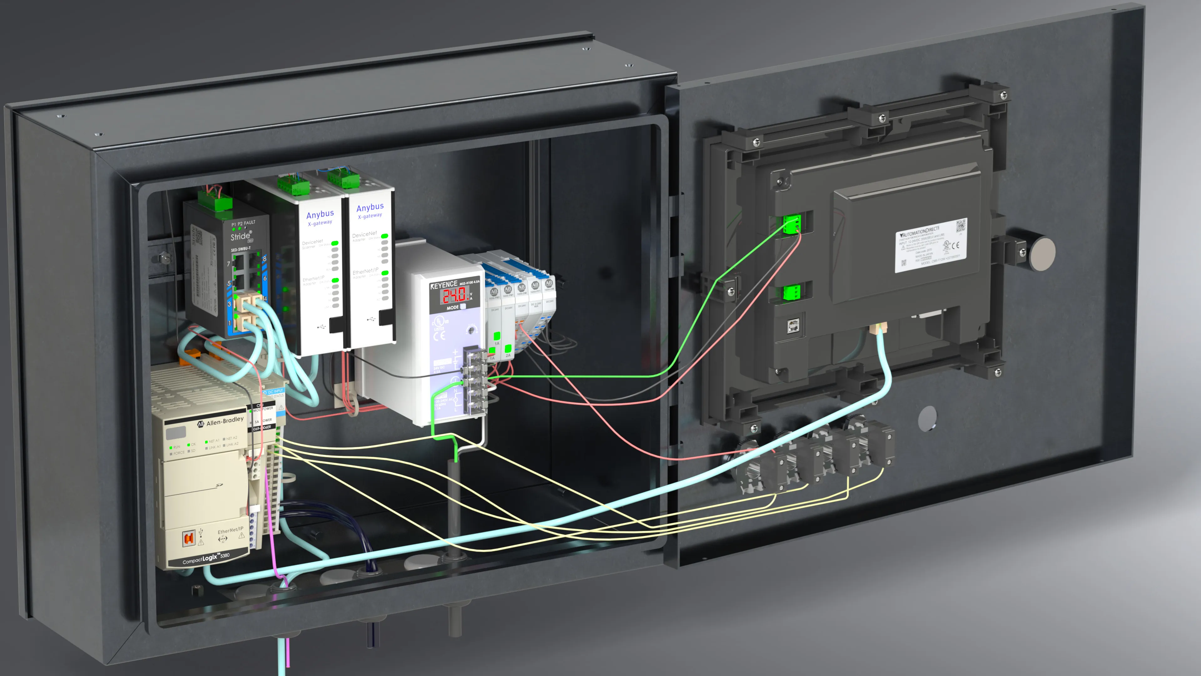
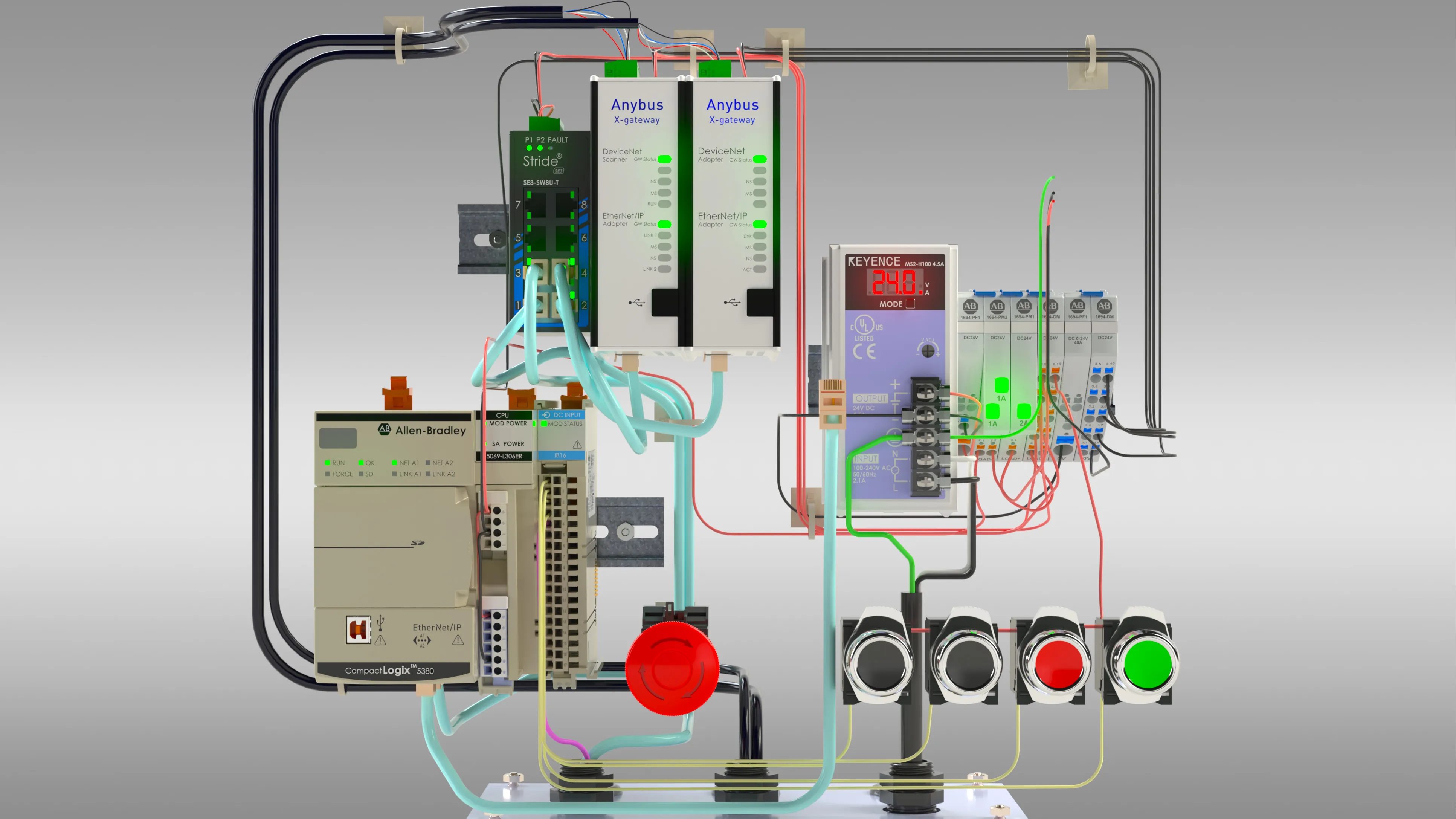
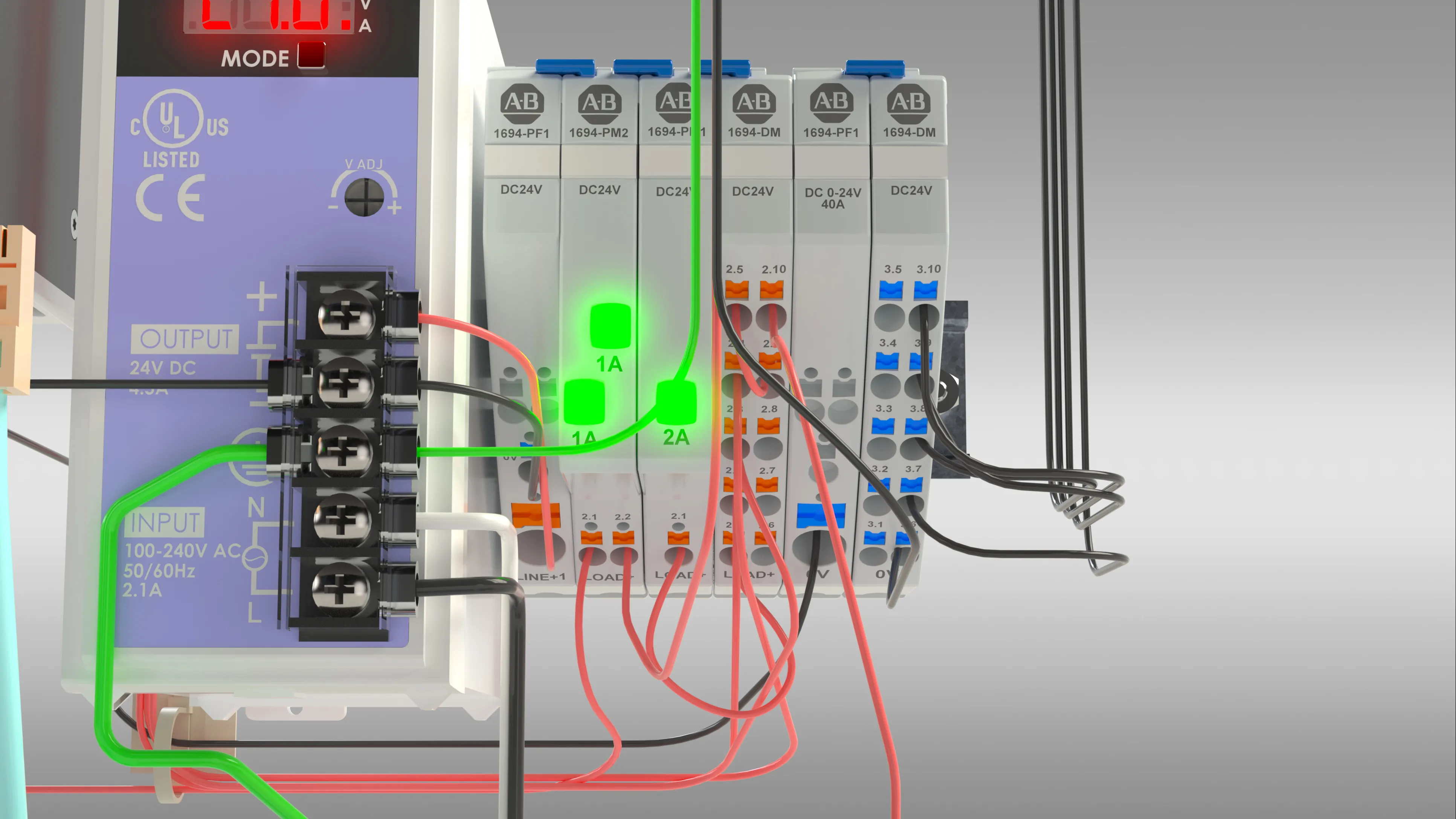
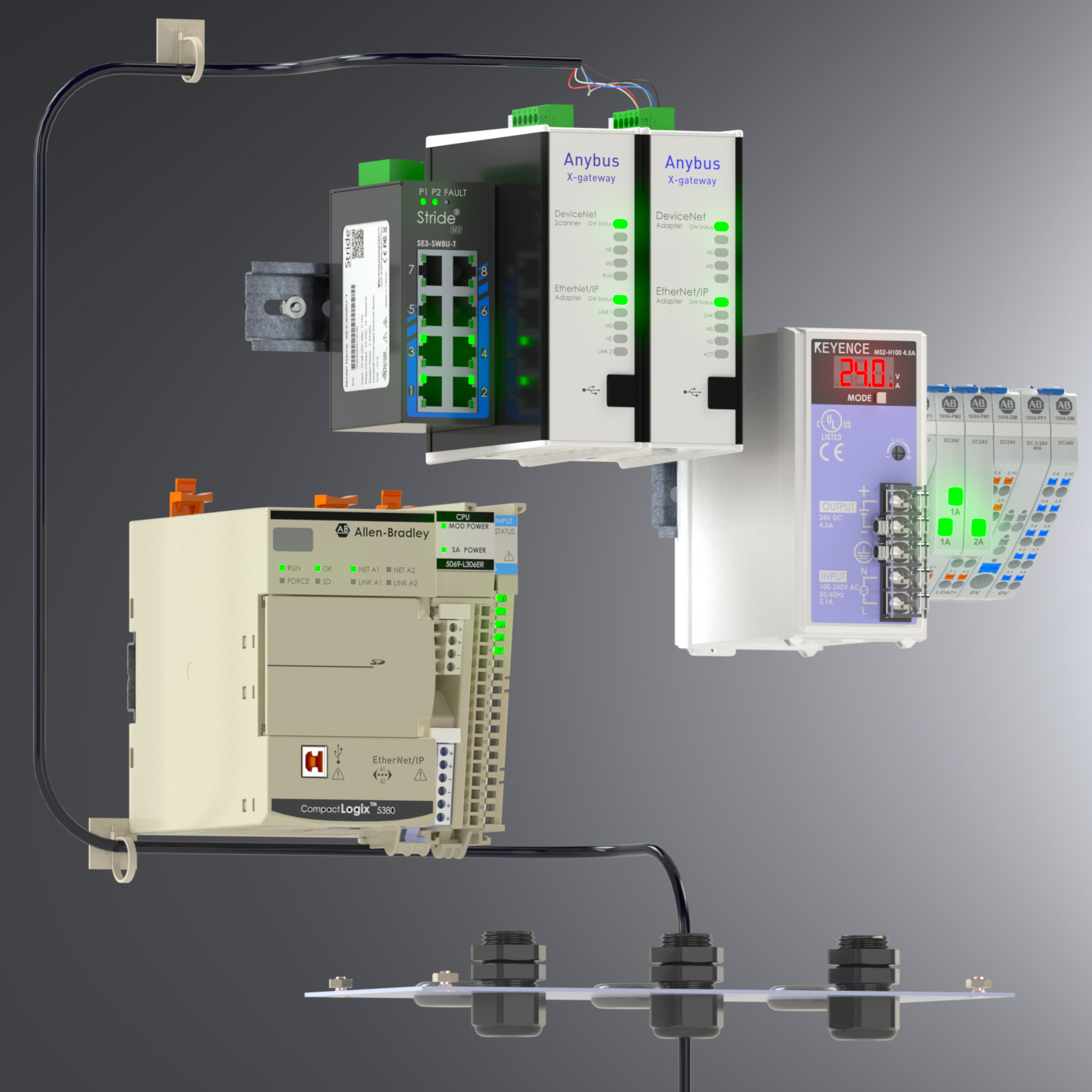
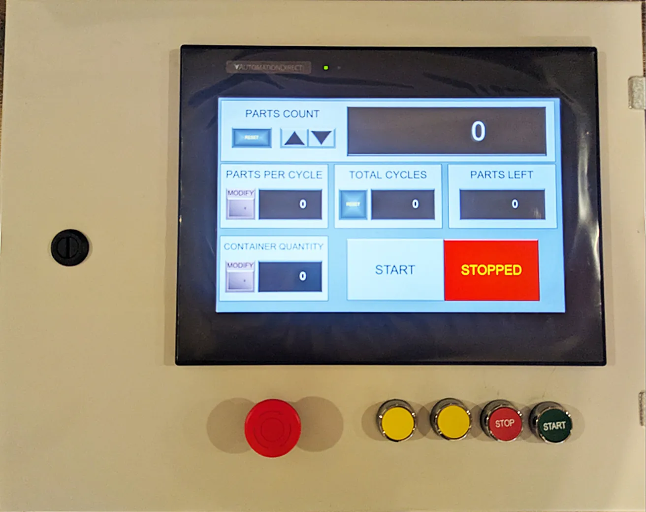
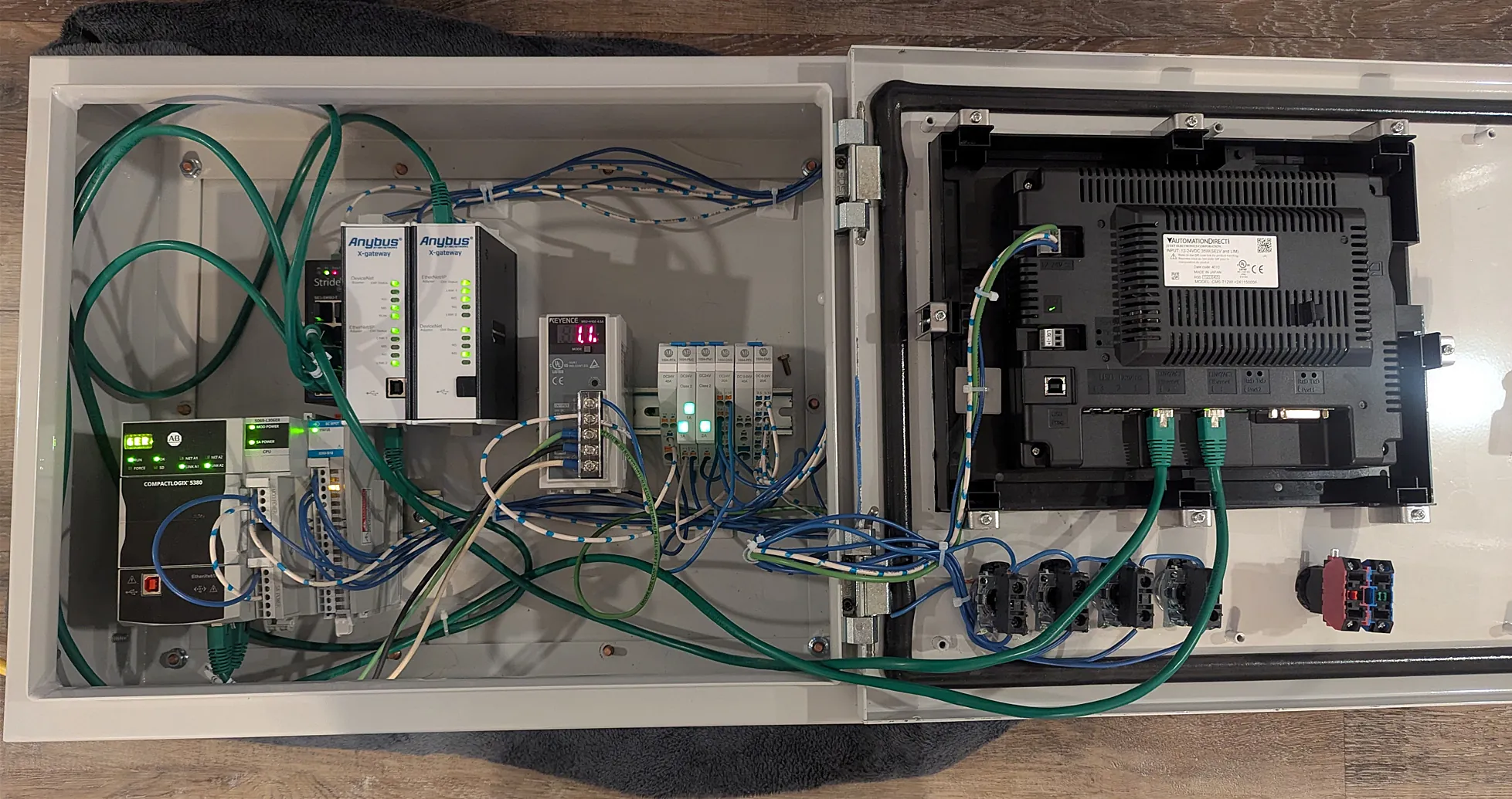
My Capstone team partnered with BTD manufacturing with the goal of interfacing devices across different industrial communication protocols. BTD tasked us with connecting their DeviceNet Fanuc Robotic Welders, Ethernet I/P ABB Welders, and multiple input modules on both protocols. An HMI was also incorporated at the front of the enclosure so that parts counts, machine cycles and remaining parts could be tracked and presented to the operator. I was given the opportunity to program Rockwell Automation / Allen-Bradley's Compact Logix PLCs using Studio 5000. I used SolidWorks to design the layout for wiring the system. This enabled the creation of a manual for the purpose of recreating the enclosed system across the many weld cells. Within the manual, each individual wire run has at least one render specifically tailored to best represent where that respective wire should be routed. It also contains a section for troubleshooting the various errors that could occur if the step-by-step instructions are not followed. This was achieved keeping within the budget allotted for the project.
DIY Ribbon Microphone
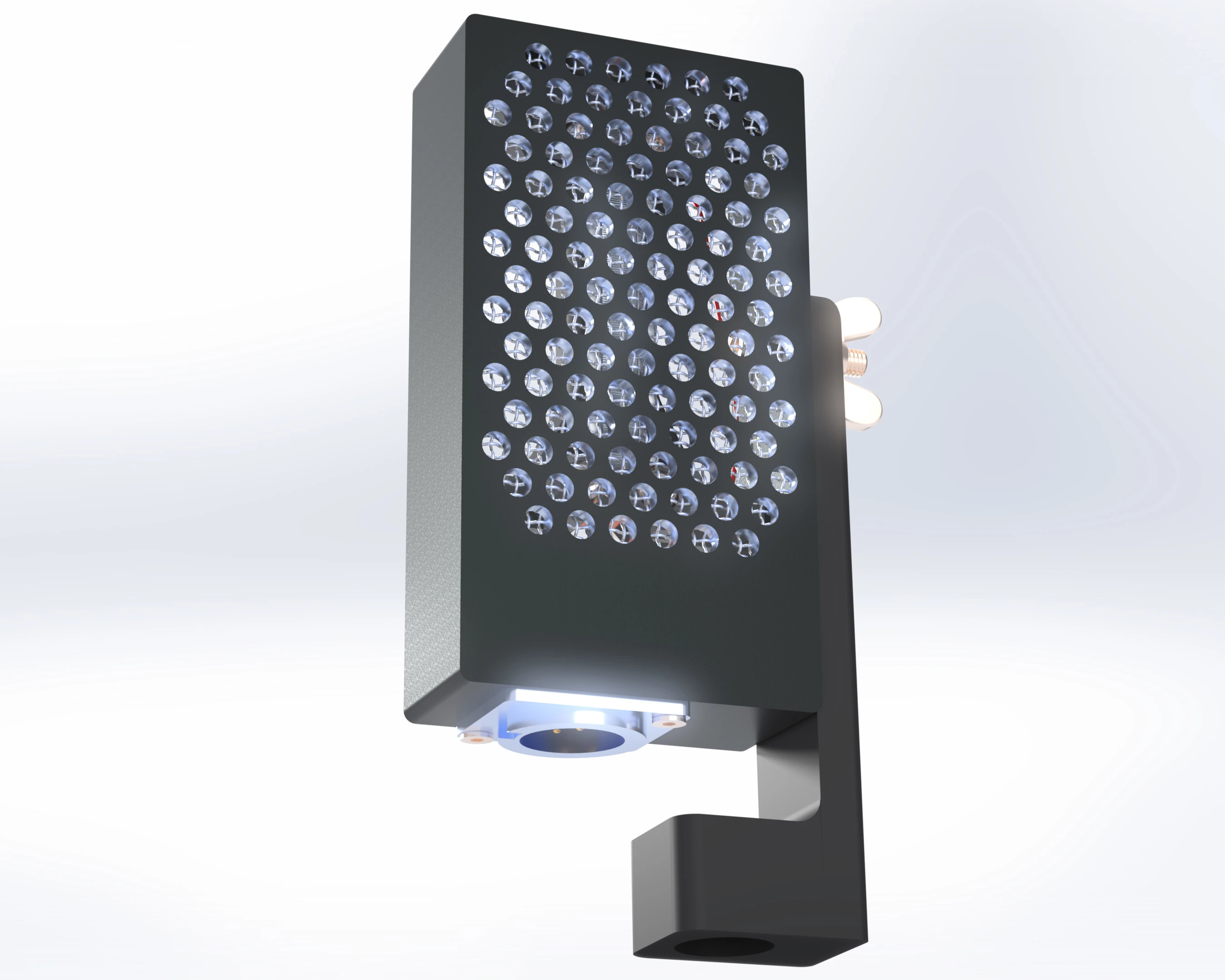
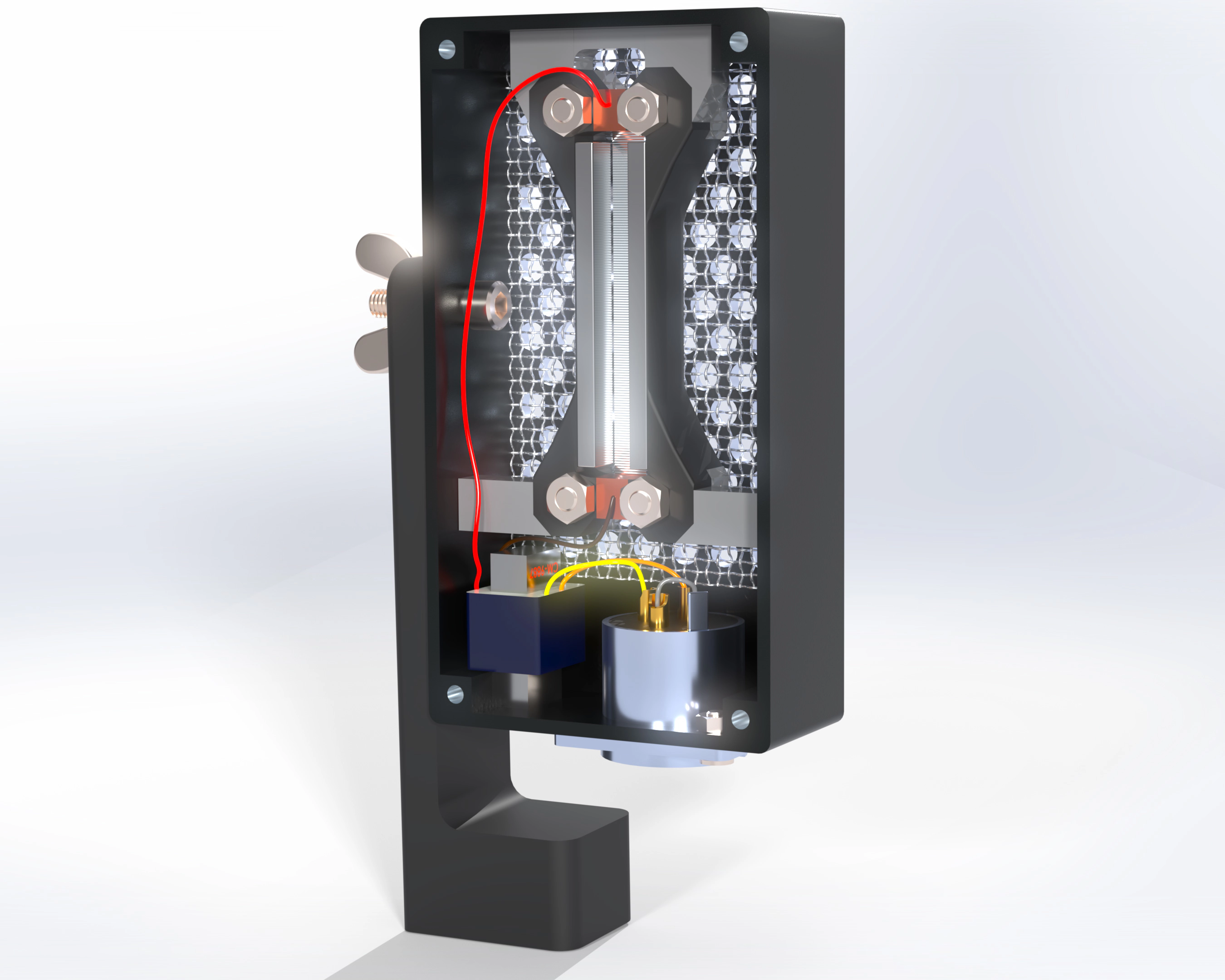
This is a Ribbon Microphone I designed and constructed. Cost was minimized by utilizing a guitar pedal enclosure for the body. A metal mesh was incorporated to further minimize potential damage to the delicate 7µm foil element (much thinner than the thickness of a human hair). Even small bursts of air will damage the element. A 3D printed device was designed and used to obtain the intended corrugation dimensions. The neodymium magnets and 3D printed capsule were designed to maximize the amplitude of the high frequency response which is often a weak point of ribbon microphones.
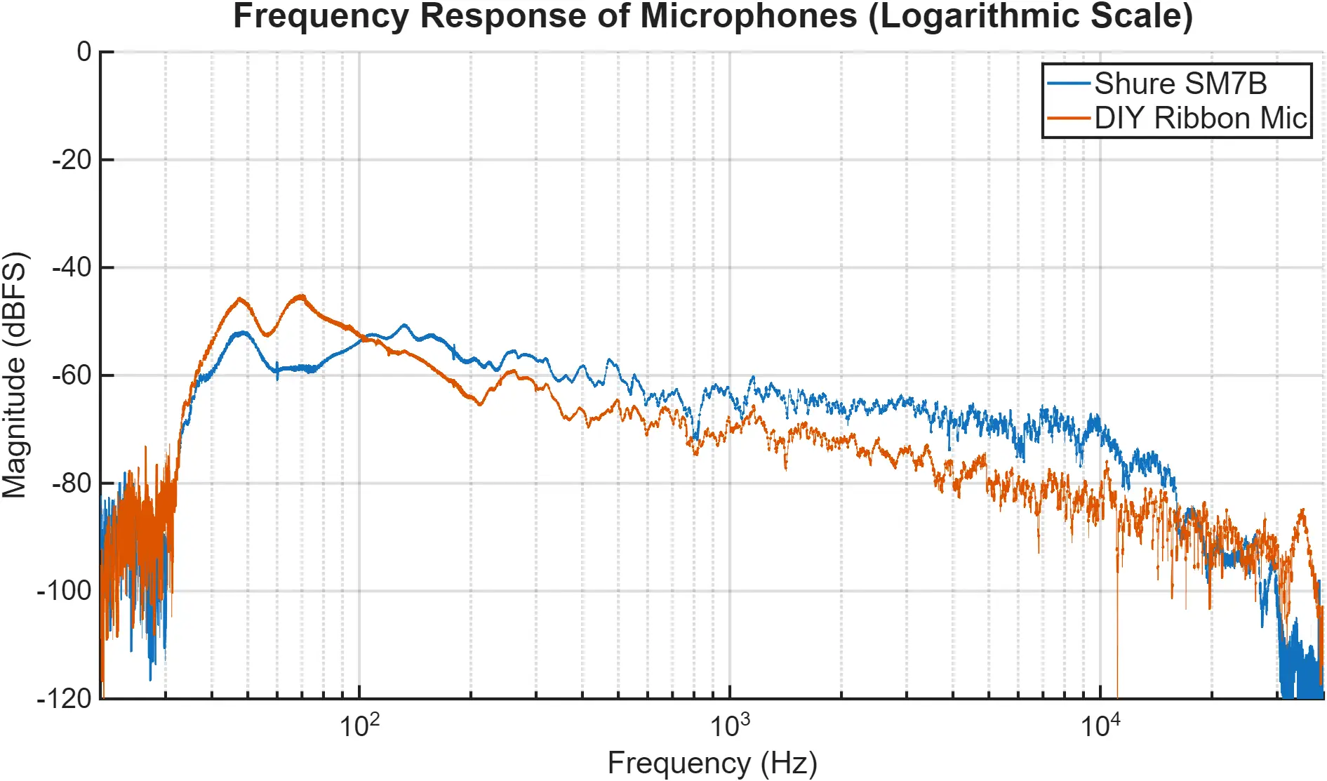
To evaluate the microphone's performance, I compared its frequency response to that of the Shure SM7B. A frequency sweep was played through a Genelec 8040A and recorded with each microphone at a 24-inch distance using identical settings. The audio files were analyzed in MATLAB performing a fast Fourier transform, converting the values to dBFS, and plotting the result.
Measurement Controls
- Recorded at 32-bit, 96 kHz to ensure accurate capture of frequencies above 18 kHz, avoiding aliasing artifacts.
- Used gobos (acoustic panels) around the microphone and speaker to minimize room reflections and ensure consistent acoustics.
- Employed a high-quality signal chain: Microphone → 500 Series Preamp → Universal Audio Apollo interface.
- Maintained identical gain settings for both microphones to ensure a fair comparison.
- Positioned microphones at a consistent 24-inch distance, measured from both tweeter and cone to capsule.
- Corrected for potential DC offset in MATLAB to ensure accurate frequency response analysis.
Conclusions
- Excellent results for the cost.
- Comparable performance to significantly more expensive large ribbon microphones.
- The use of a guitar pedal as a microphone body did not compromise performance to the degree I initially anticipated.
- A device to assist in cutting the 7µm foil element would likely improve the result.
- Implementing a shock mount would minimize noise from vibrations transmitted through the microphone stand.
- Although the frequency response graph suggests otherwise, the ribbon microphone exhibits greater sensitivity to low-volume sounds compared to the dynamic Shure SM7B.
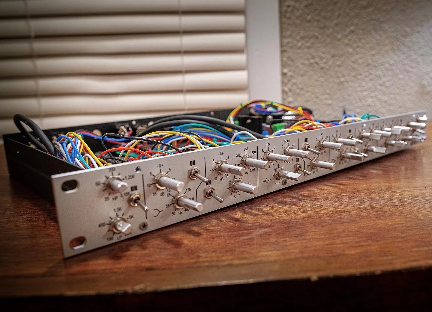
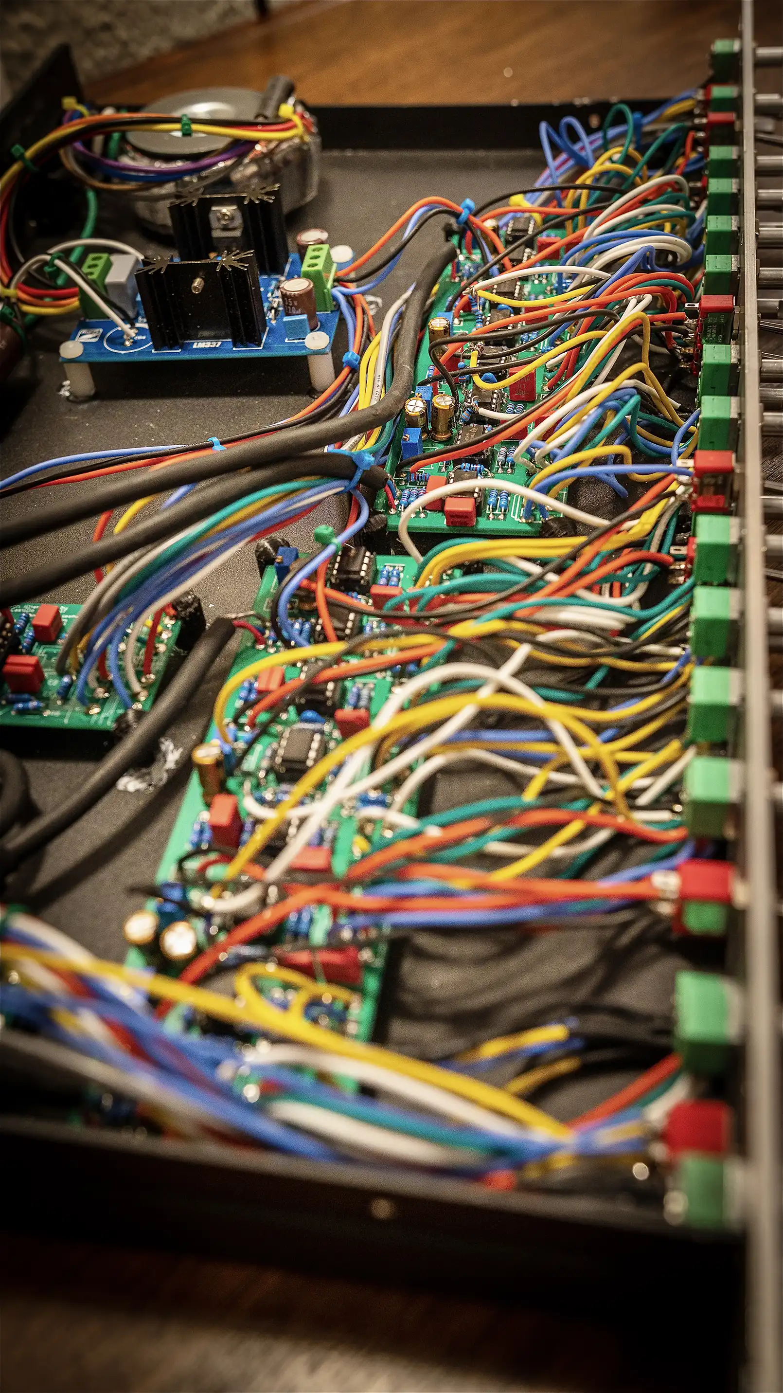
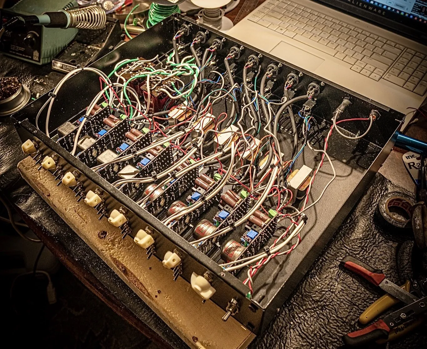
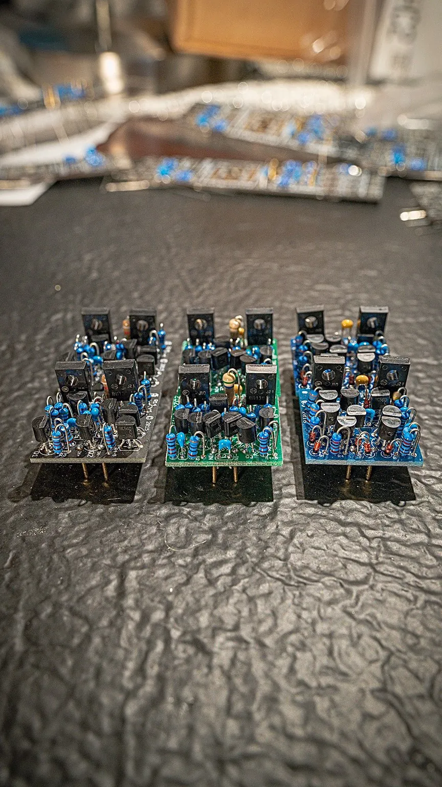
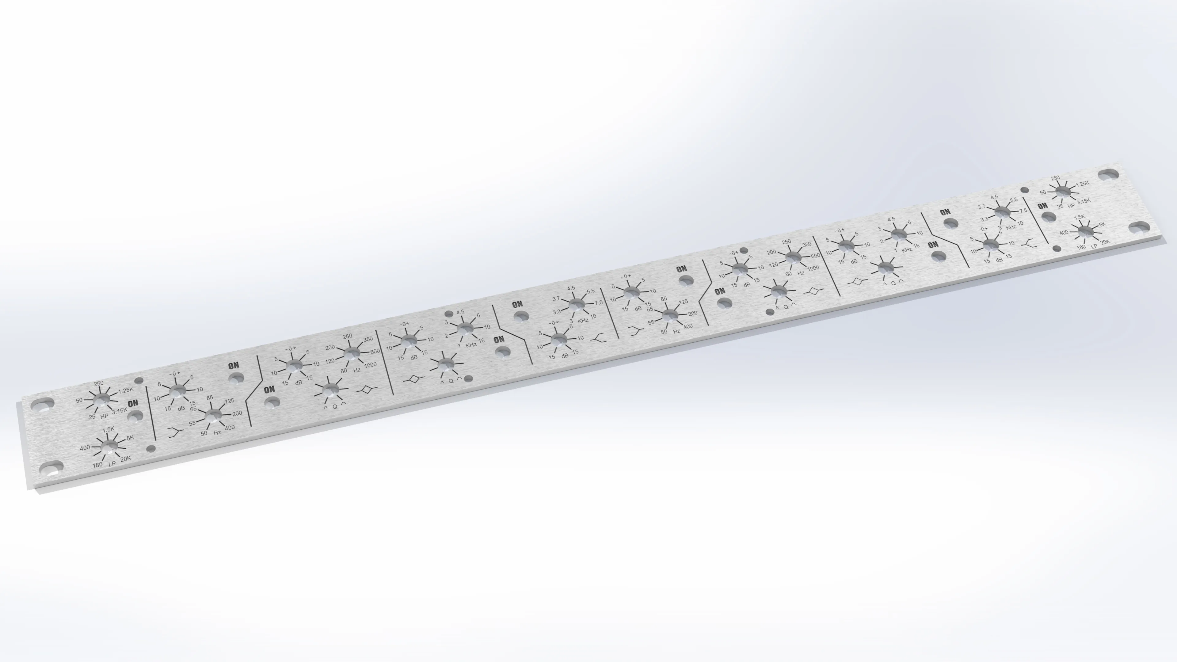
Various DIY Analog Audio Projects
These are a few of the many analog audio projects I have done over the years. I am particularly passionate about analog audio. I find that the results I get from them in a recording, or a mix, is just not something I can get from plug-ins in the same capacity. I am certain this is mostly because of the extreme attention to detail in component selection throughout the process. I find that plug-in designers tend to choose to model many of the same units. I do not generally stick to a completely faithful reproduction of classic hardware. In many cases you simply cannot acquire the various transistors that were used almost half a century ago. Designs often require modification to accommodate the transistors used today to get many of these circuits to function. These sorts of projects really teach you that there is so much more to what capacitance a capacitor has or what resistance a resistor embodies. You must take into consideration things like PPM, ripple current, or ESR among other factors. I have come to understand that certain parts of a circuit benefit tremendously from spending a small percentage more monetarily on quality for peak performance.
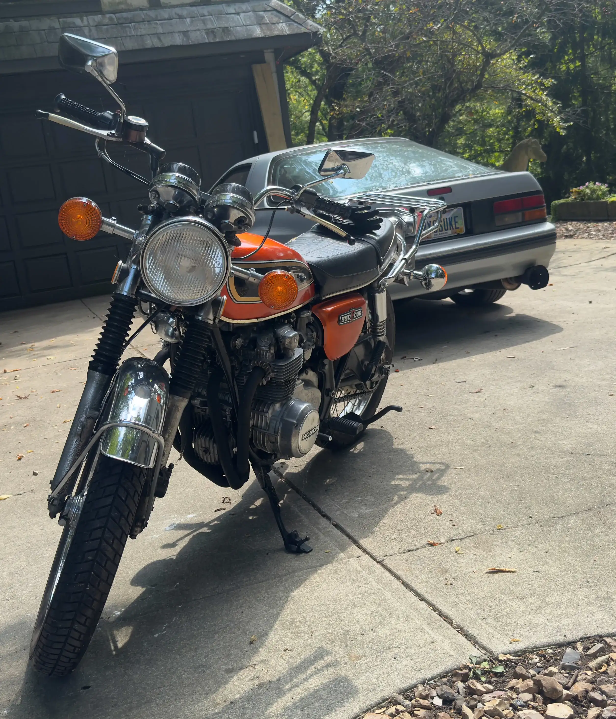
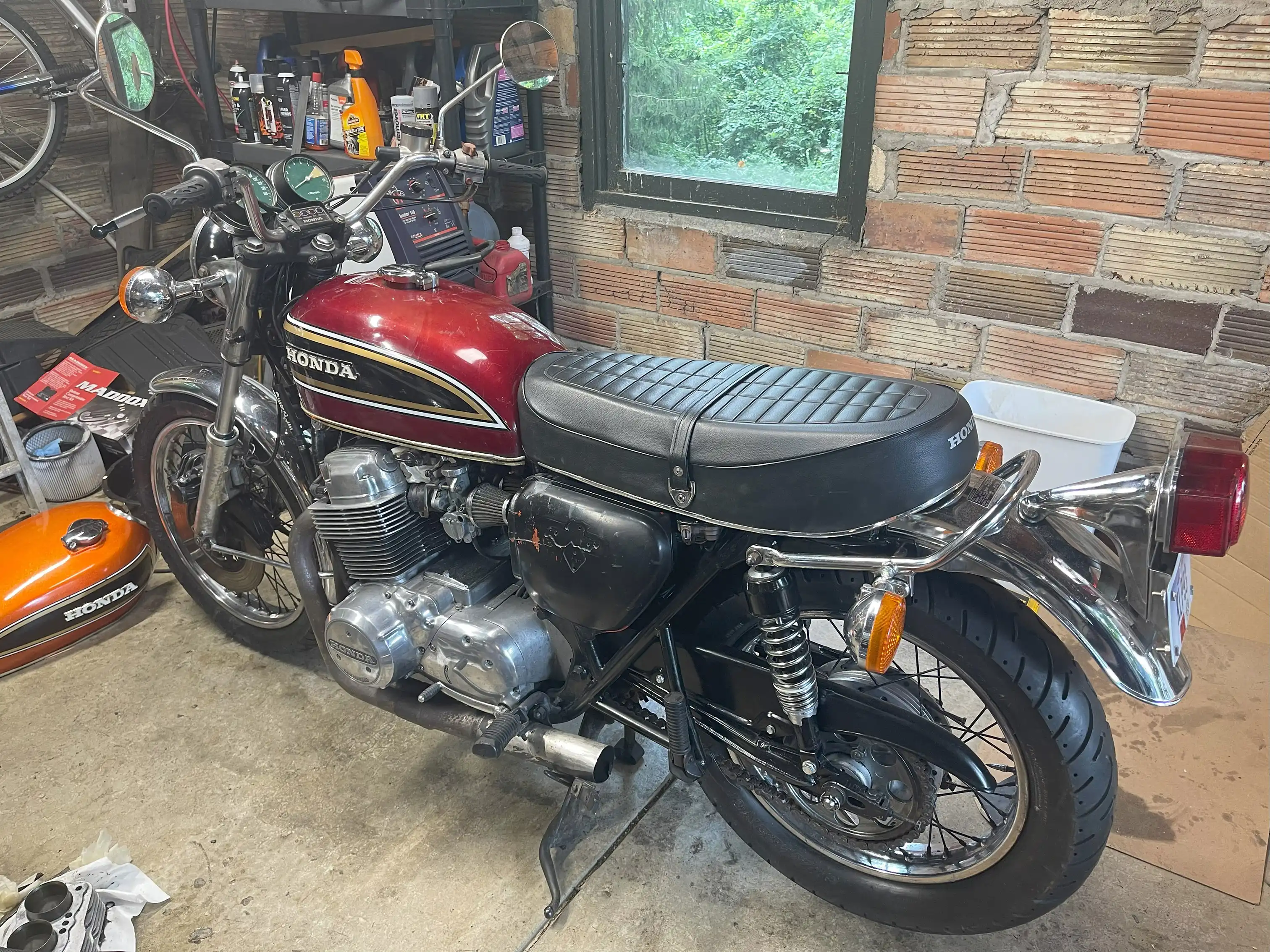
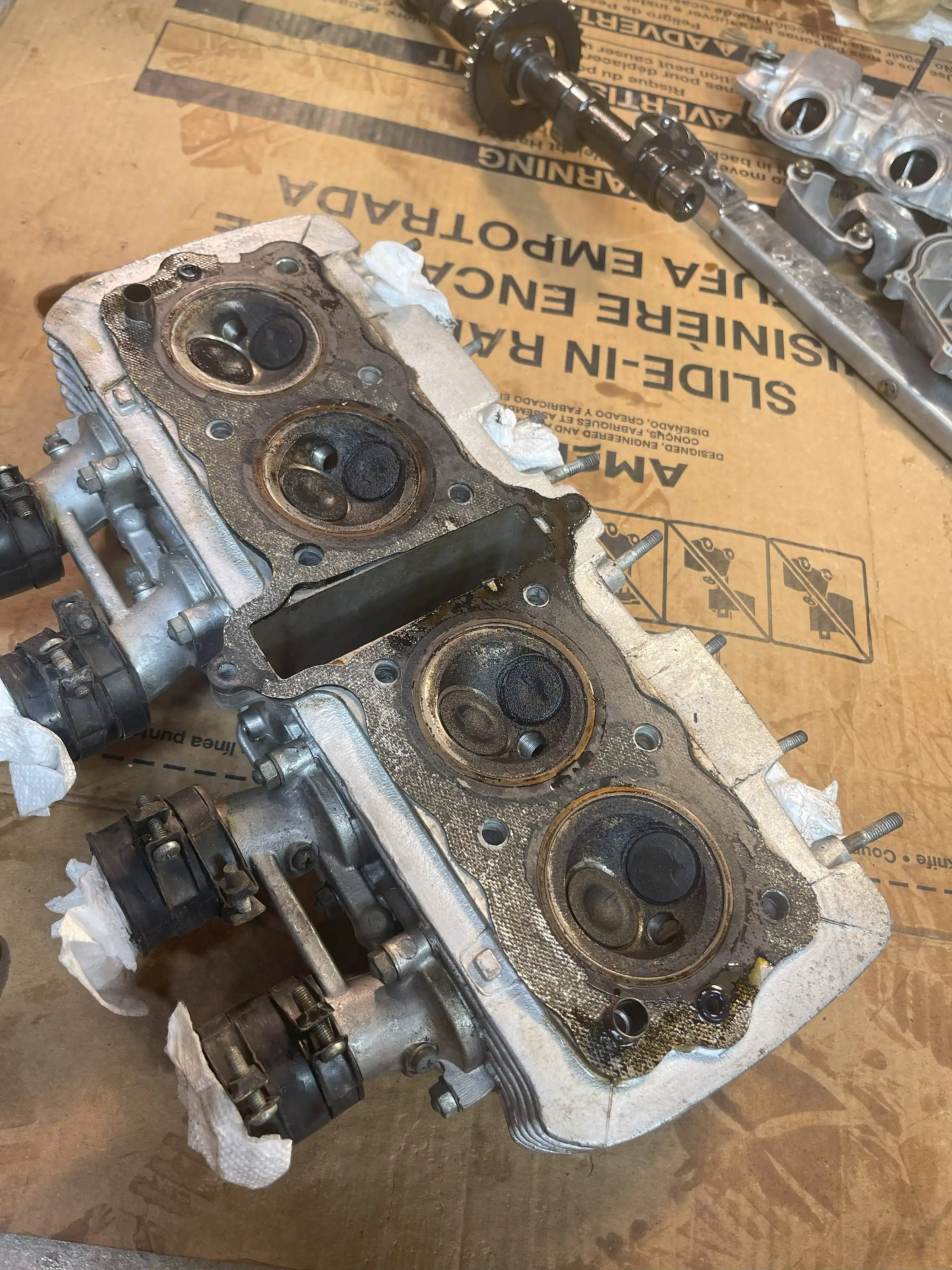
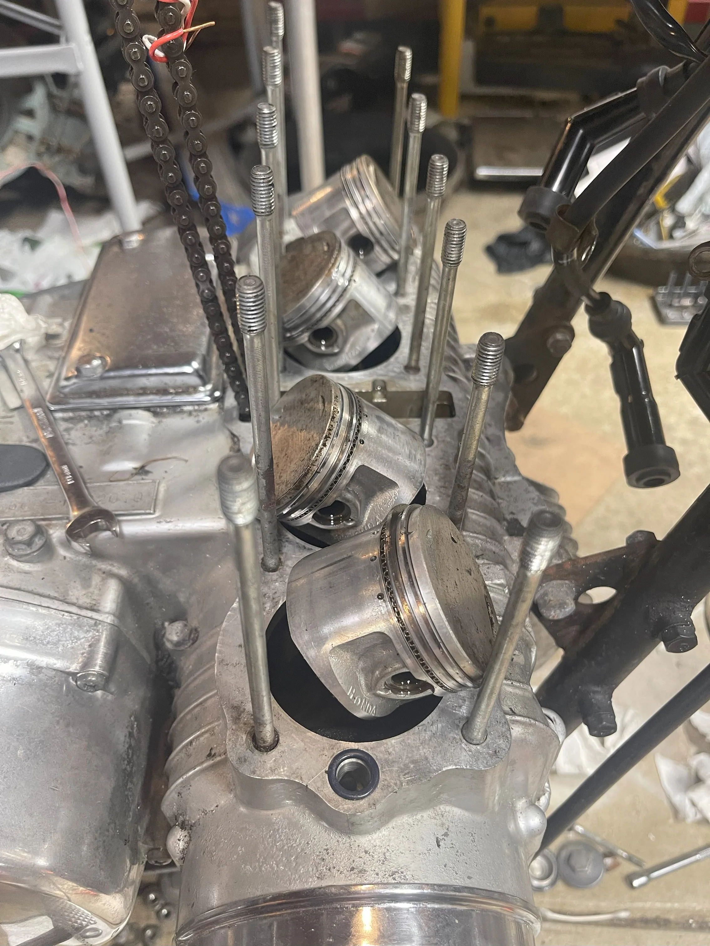
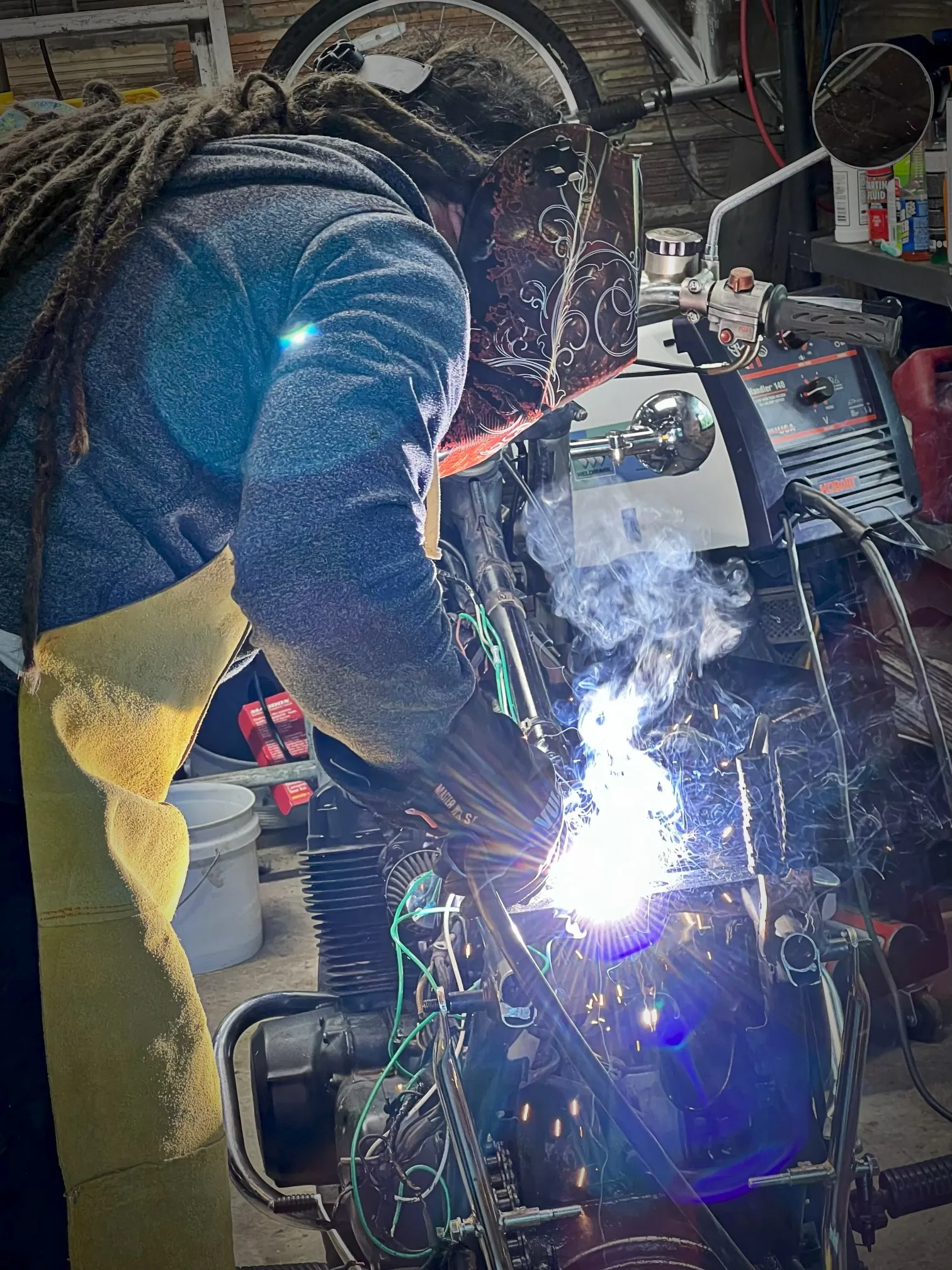
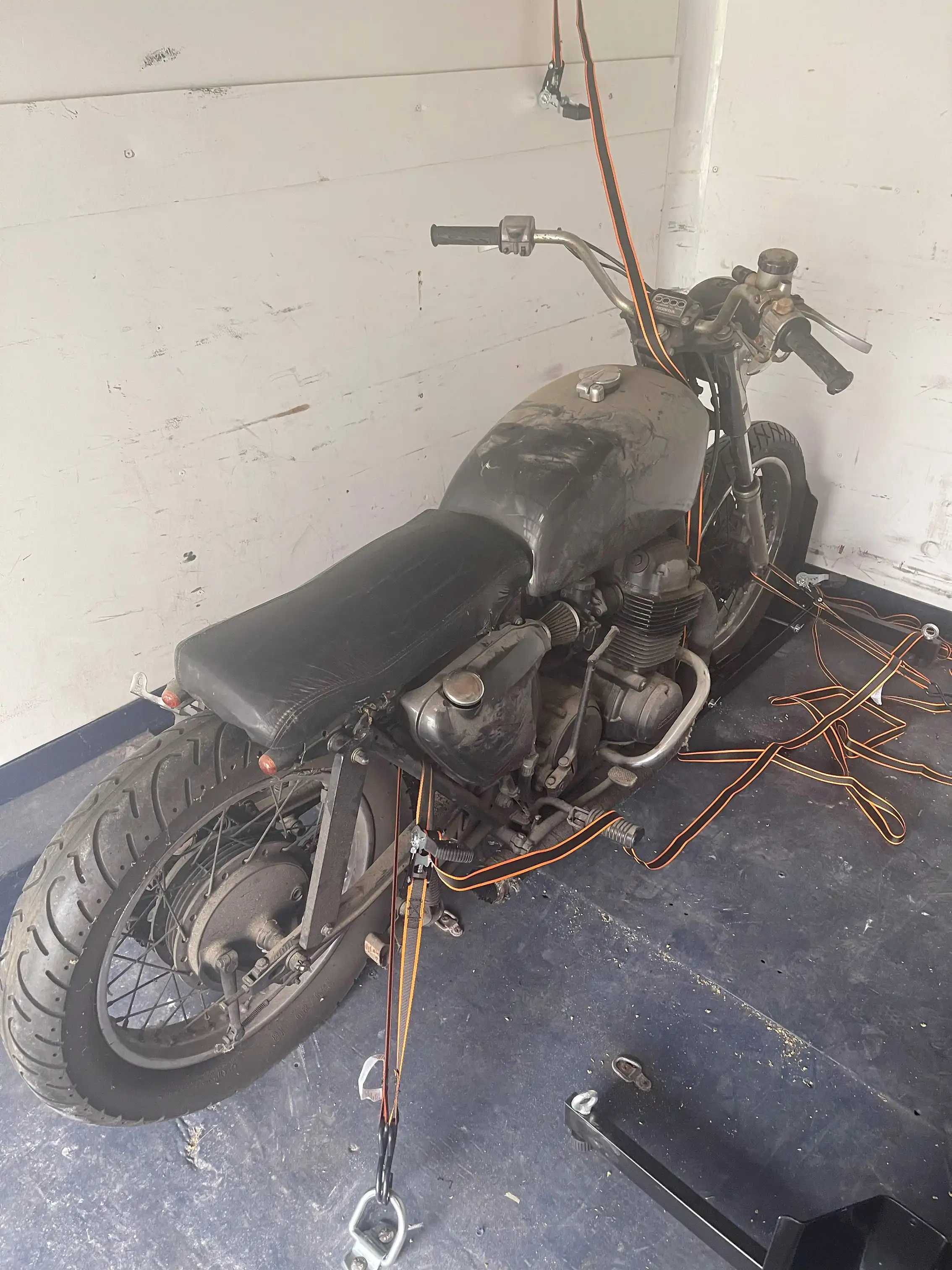
Motorcycle Rebuilding
These are two vintage Honda motorcycles from the 1970's that I bought and had to do a significant amount of work on restoring. When I started this project, I never took on any engine work. I also did not have anyone to teach me how to do it. So, throughout the process I had to learn about every step by myself. I learned a great deal from the entire process. Especially since I wanted to ensure these were both safe to ride, I had to trouble shoot everything about these motorcycles. Both electrical and mechanical. Not one detail was spared to ensure their proper function. I got to try my hand and welding which came out solid. I learned about the older electrical systems that Honda deployed. It was especially interesting to learn more about older ignition systems. I learned how to work on, rebuild, and sync carburetors. Which can make you feel spoiled with modern electrical injection systems. During this project I used a decision matrix to evaluate the cost of different components in the repair. This enabled me to stay within the overall budget I gave myself for the rebuilding process. Both motorcycles came out working very well. And there are many more things I learned to do than are mentioned here. I was able to ensure my dad got to enjoy this 1976 Honda CB750 four at the end of this process too. The 1975 Honda CB550 Four is the motorcycle I ultimately learned how to ride on. Honda did a fantastic job engineering these motorcycles. I consider them to be true classics.
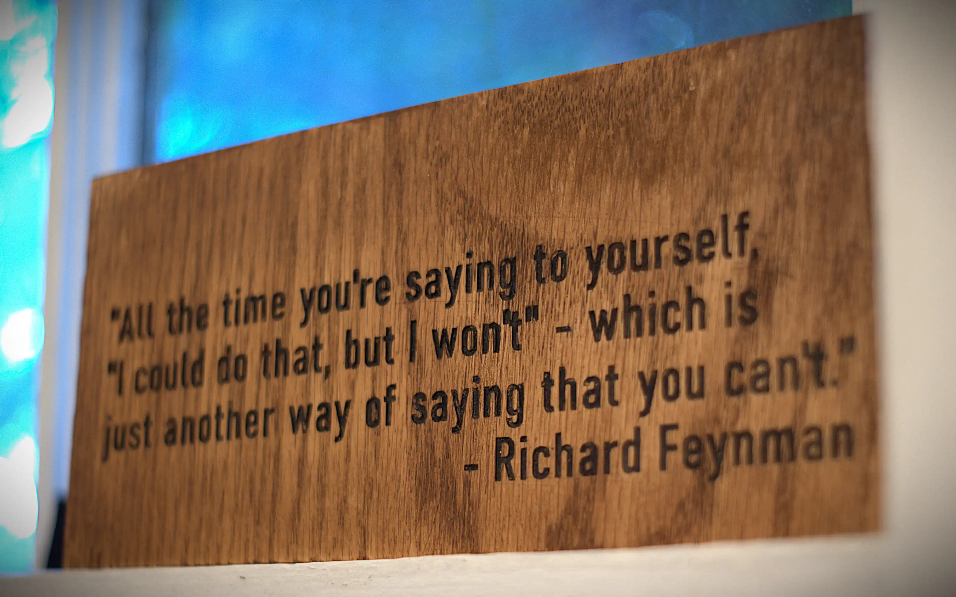
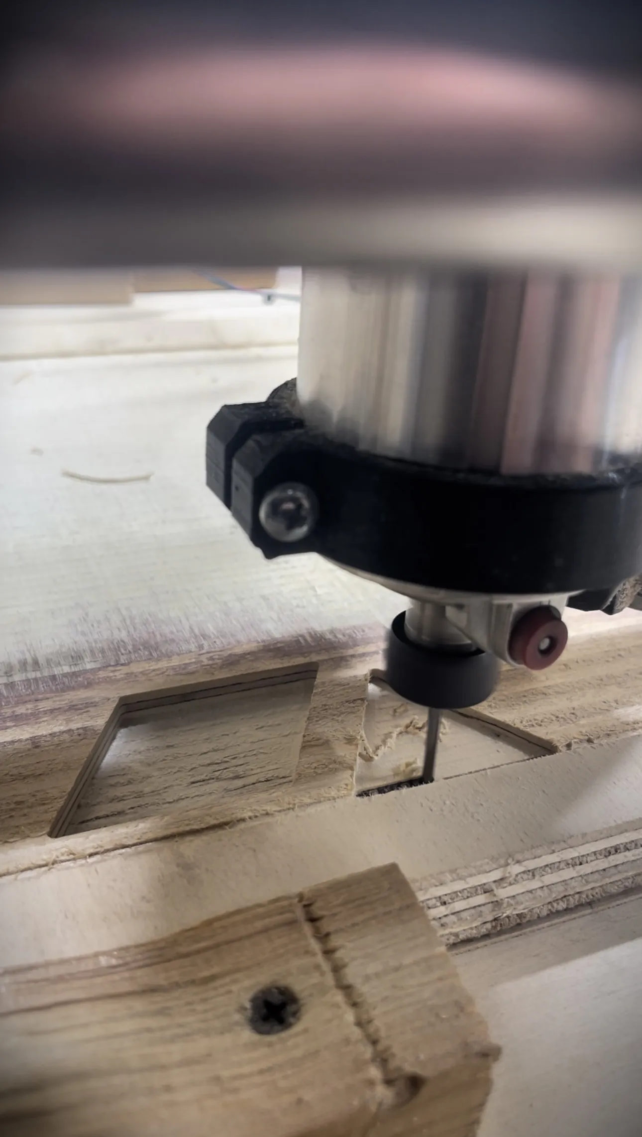
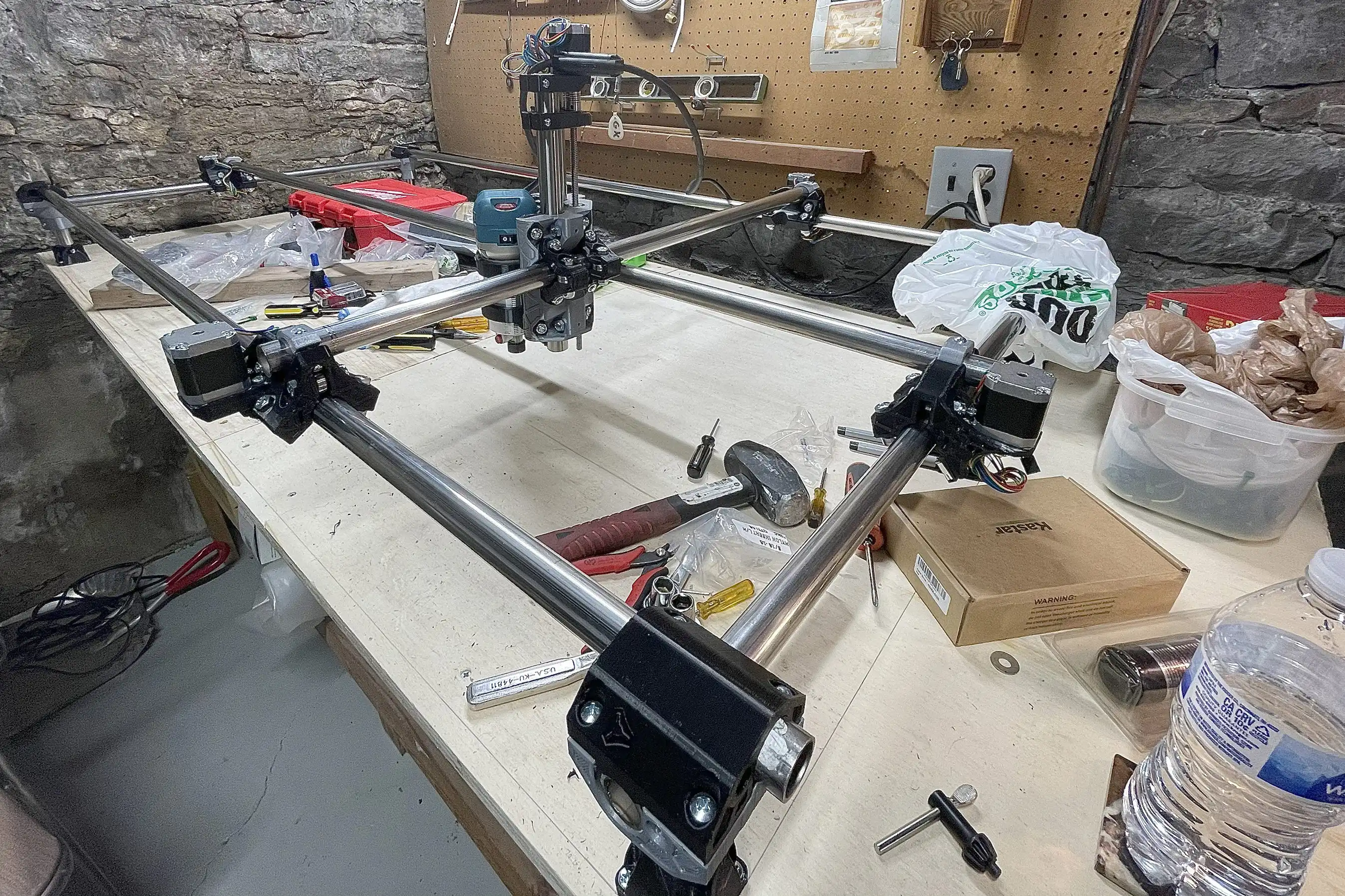
DIY CNC Machine
This was a project I undertook to be able to speed up the process of woodworking for myself. The CNC is made using 3D printed parts and stainless-steel cold rolled tube. The usable area is roughly 2 ft by 4 ft and about 6 inches of depth. I used Marlin to program the controller board which is used in conjunction with Octoprint to run the machine. Most of the time I use SolidWorks to design the files and import those files into CAM software to set up the various required settings to run each job. Overall, I've been satisfied with the results I get from it. Even more so when I consider how little the entire machine cost to build.
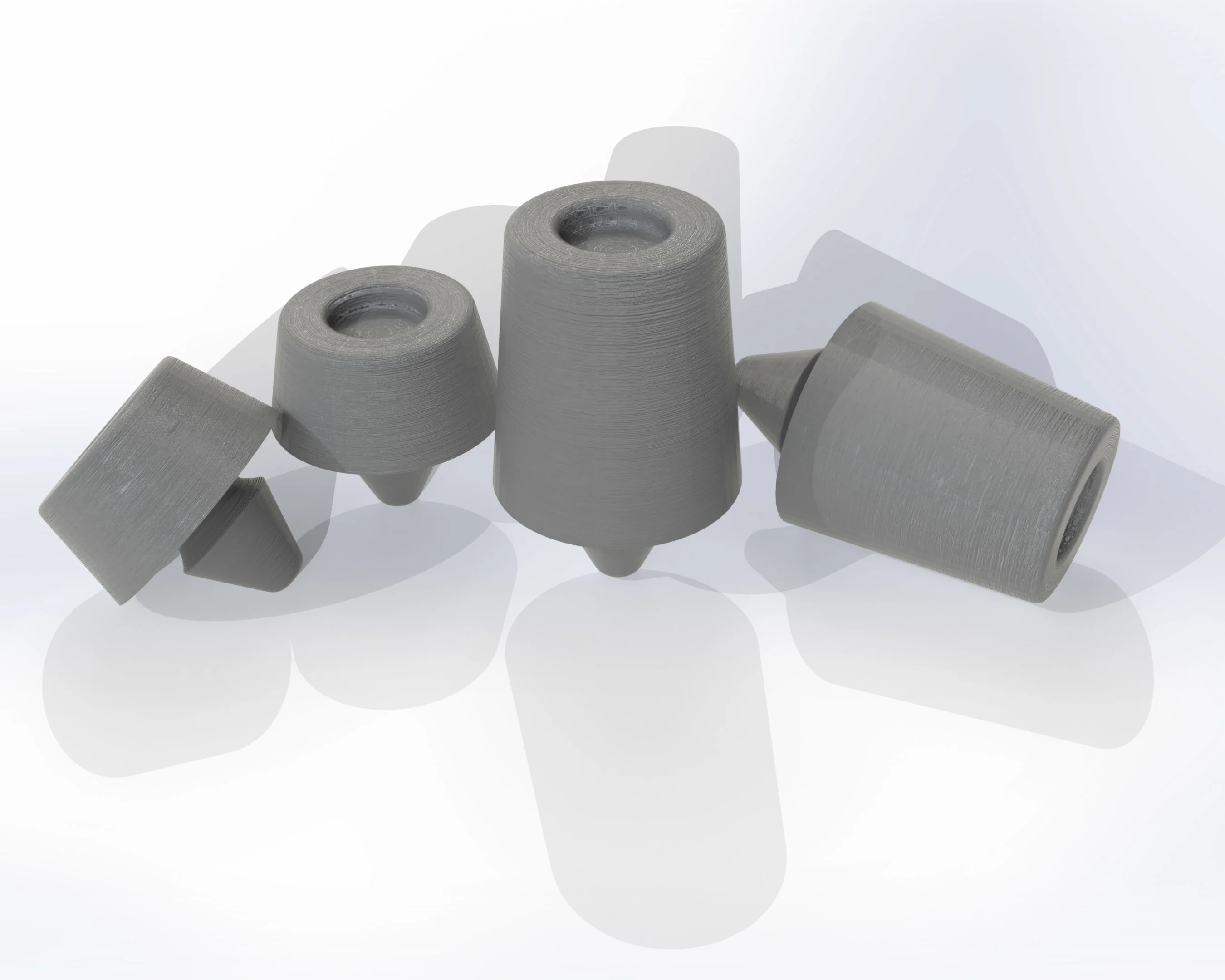
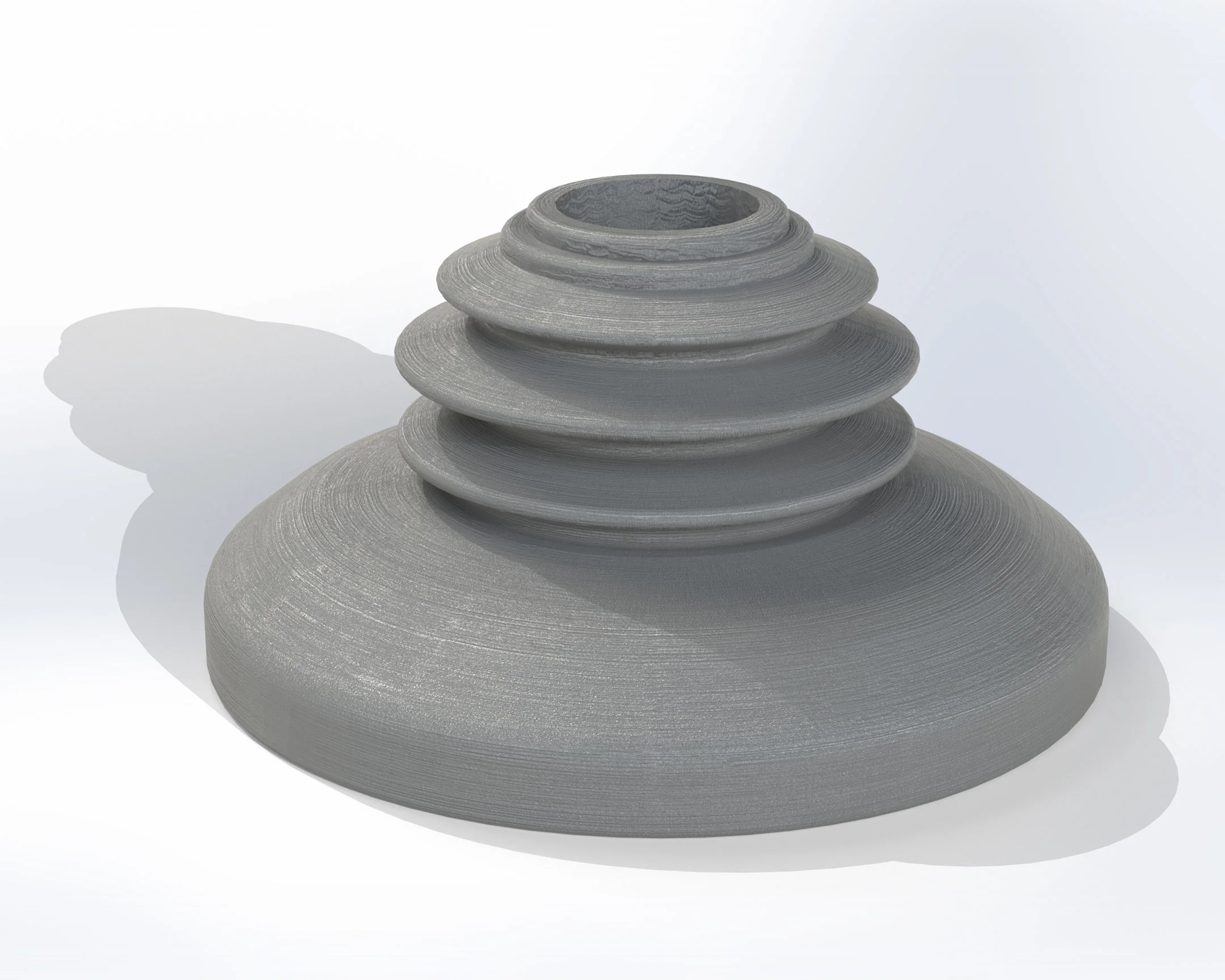
3D Printed Lens Hood
A 3D printed vented lens hood for a rangefinder camera. Specifically optimized for the Industar-61 L/D M39 mount 55mm F2.8.
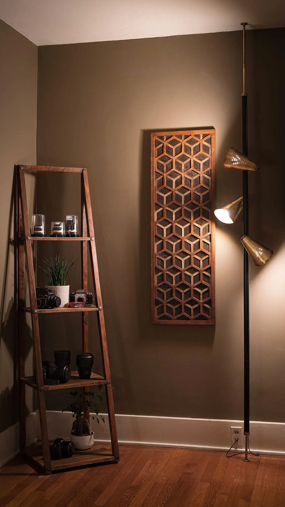
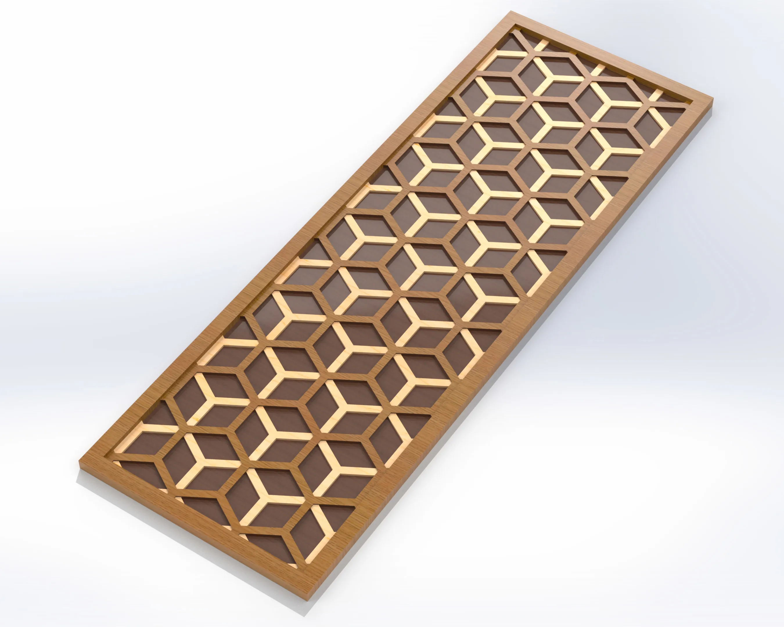
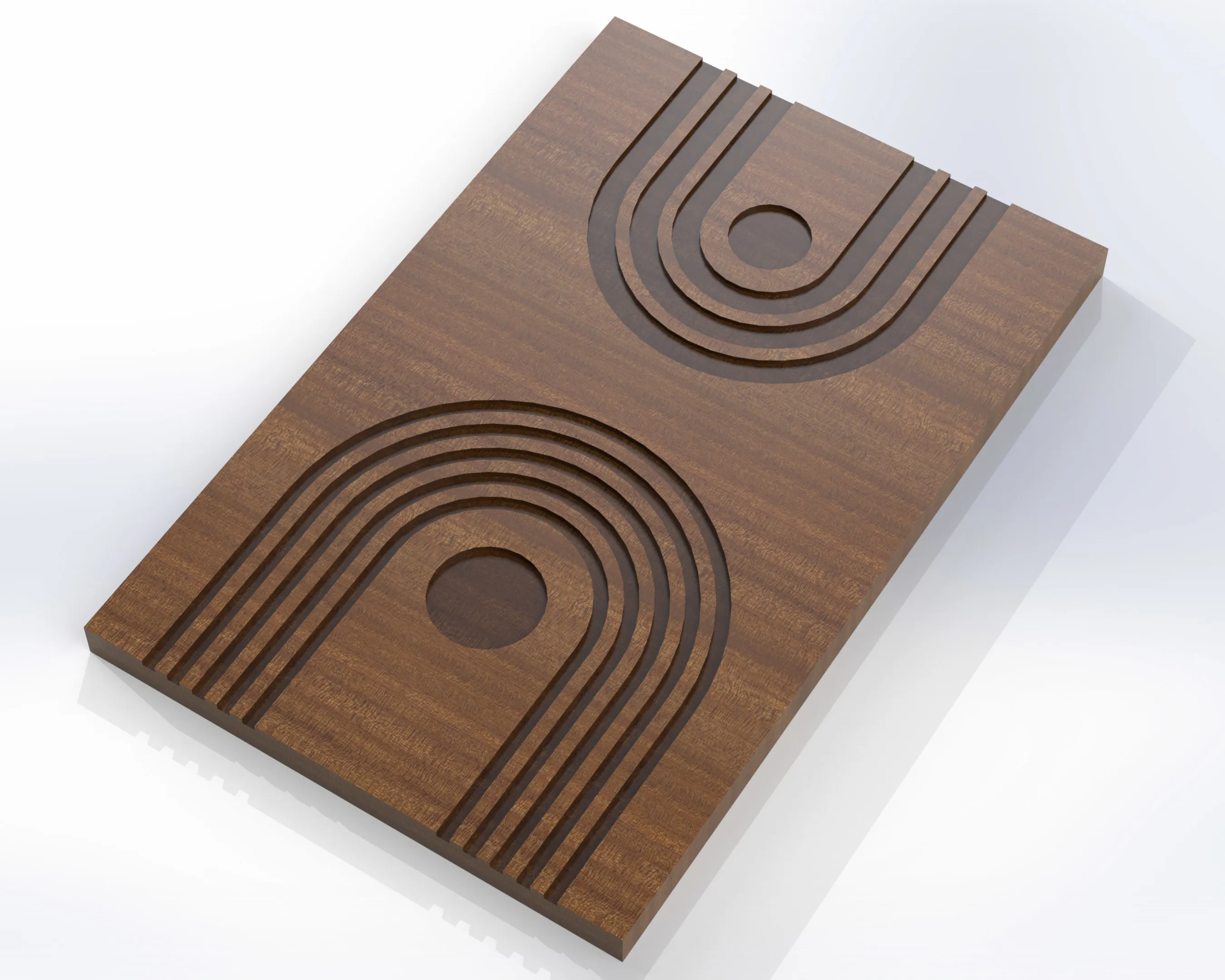
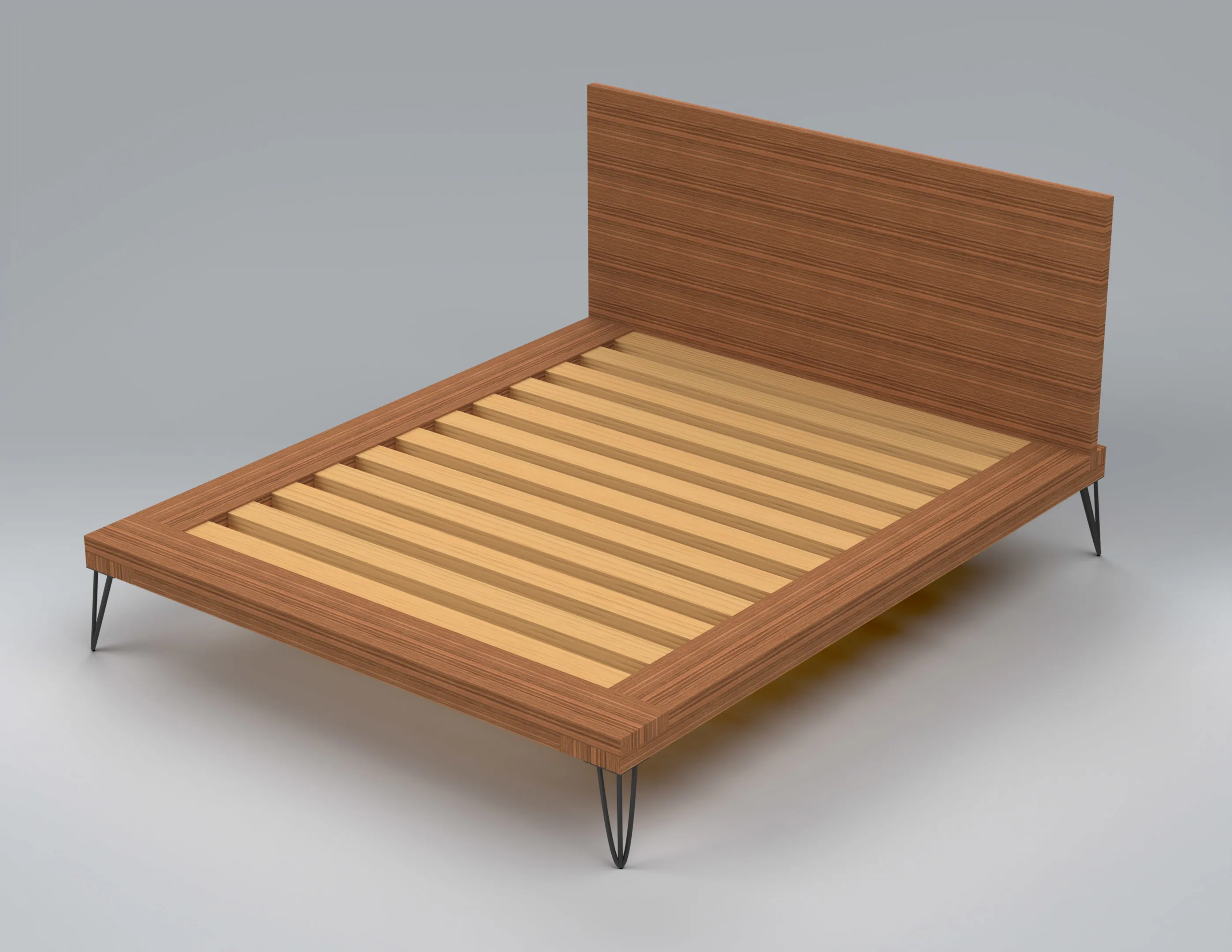
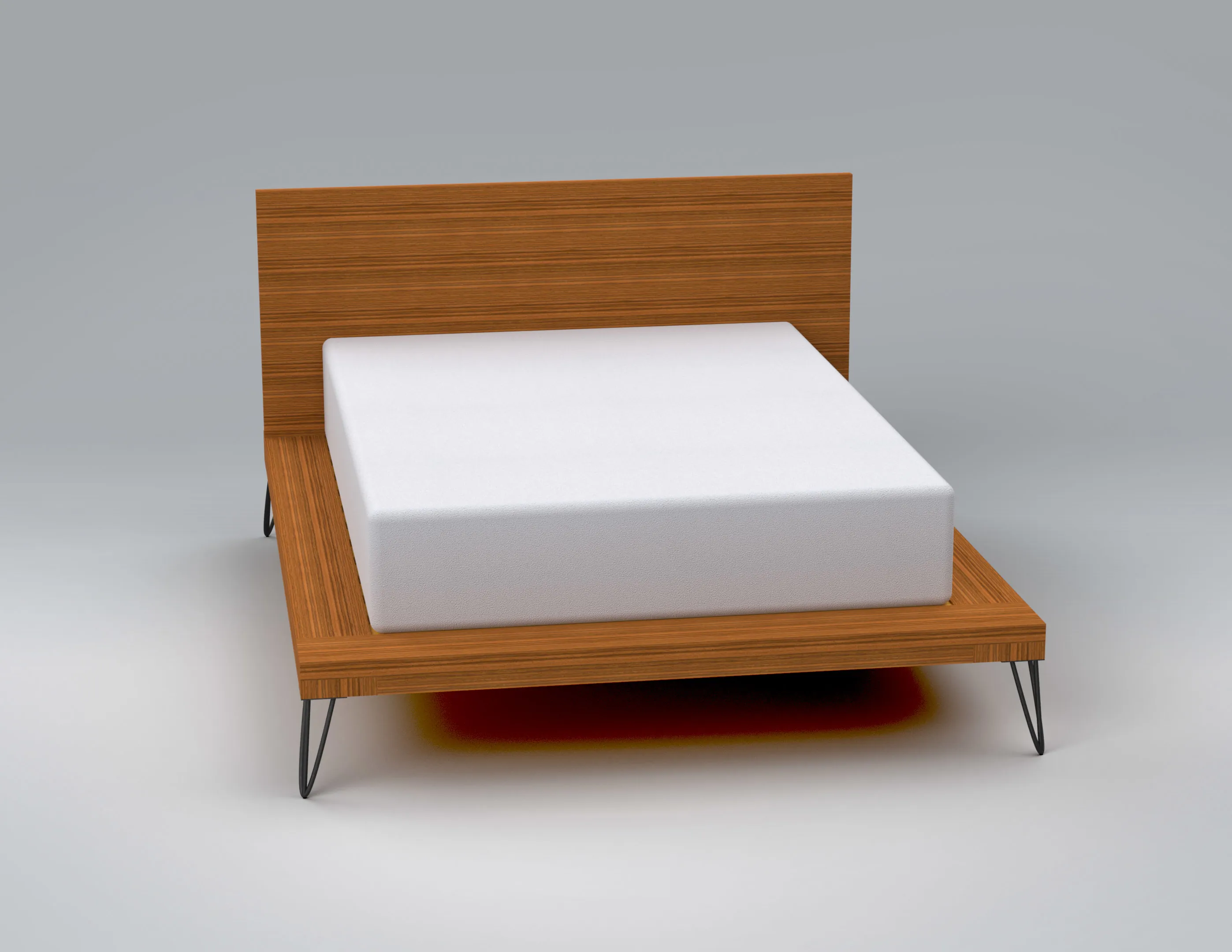
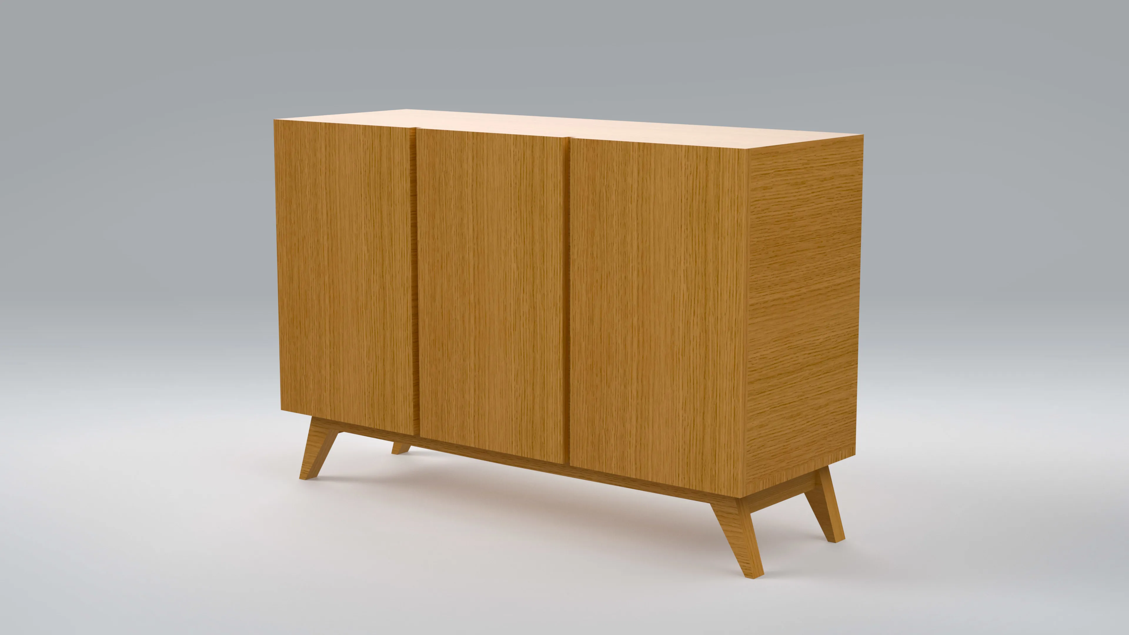
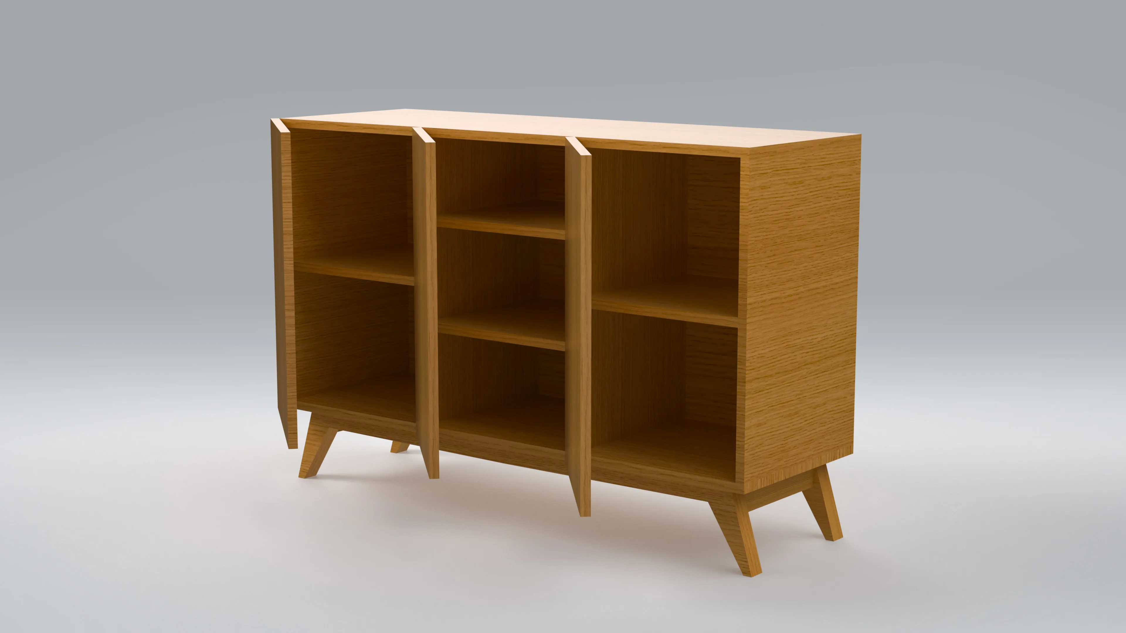
DIY Furniture
A couple pieces of furniture designed in CAD. I created each of these. The bed frames half-lap joints were done on my CNC. I fabricated the dresser by hand.
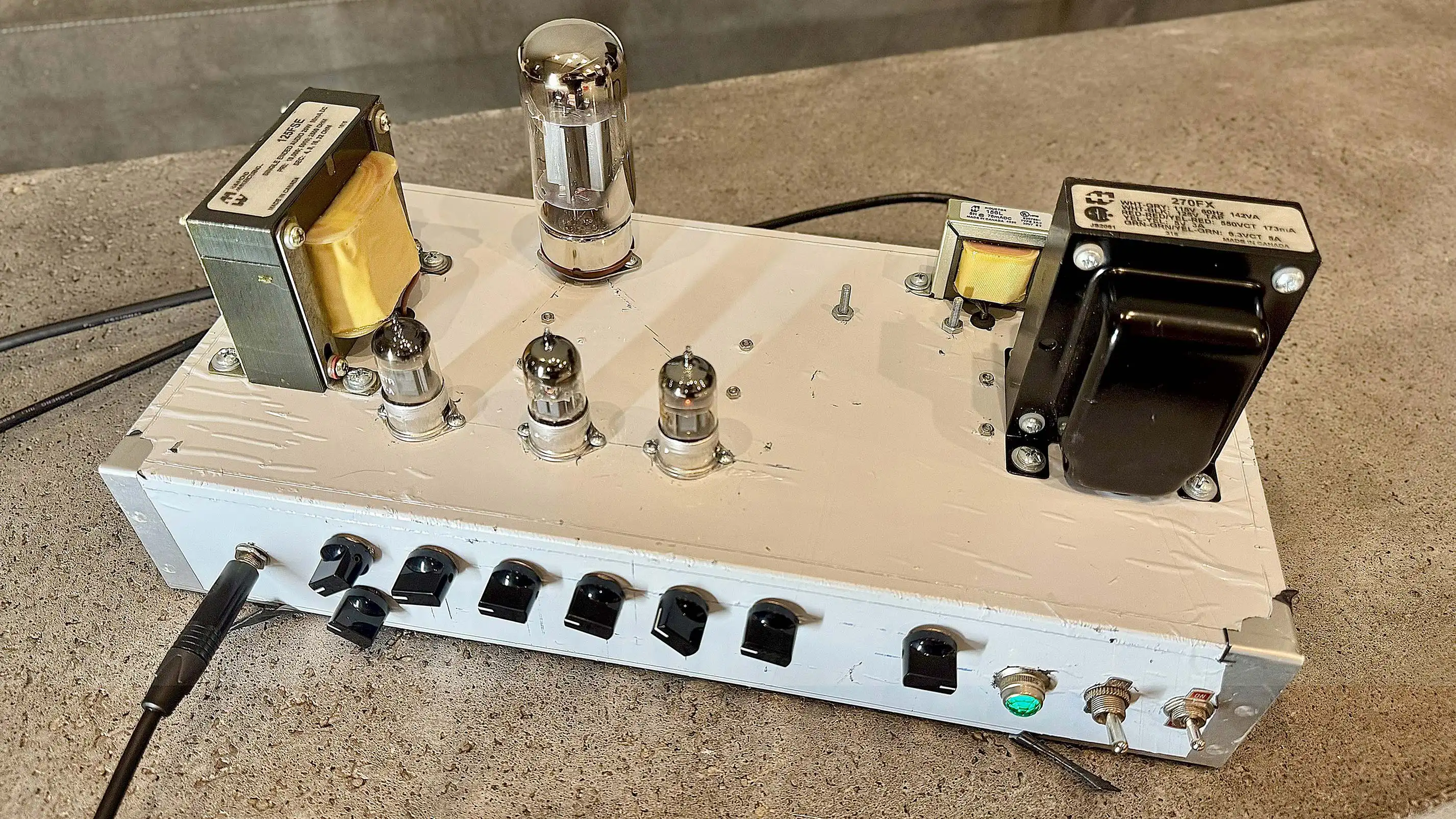
DIY Guitar Tube Amp
This is a tube guitar amp that I designed and built myself. It uses 3 12ax7 tubes in the preamp section and a single 6550 tube for the output. Using the 6550 output tube it runs at just about 20 watts of output. Which is plenty loud for a practice amp. The output tube has a bias pot so that the amp can be altered to run on other tubes like a EL34 or a 6L6. I had to take great care in building this as it is connected to mains power and the power transformer outputs 550V. I used Orange Drop and Mallory for the film capacitors, silver mica capacitors where needed and Nichicon's for aluminum electrolytics. I have a few more modifications to do to the amp overall to make it a bit more versatile. I plan on modifying the design to have a 4th 12ax7 tube and perhaps a channel selection for a cleaner tone on top of the high gain. Overall, I am quite pleased with it and after implementing those modifications I plan to mount the amp in a wooden enclosure.
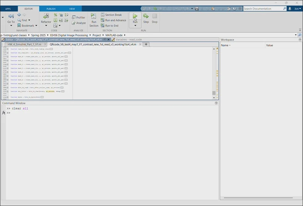
MATLAB QR Code Reader
This is a QR Code Reader I programmed in MATLAB. The program uses no built in MATLAB functions from the Image Processing Toolbox. This was to intentionally add a greater level of difficulty to the project. It performs image resizing via a normalized inverted gaussian kernel in addition to image thresholding, orientation checks, and orientation corrections. The QR Code masks are generated based on the detected version number of QR Code. The program can identify which mask is required for a given QR Code and uses the correct mask in the “de-masking” process. It also has Reed-Solomon Error Correction implemented. This allows it to utilize the error correction built into QR Codes preventing the intended message from being disrupted via a poorly scanned QR Code or damaged QR Code. If a URL is detected it will also prompt the user if they wish to open the link.
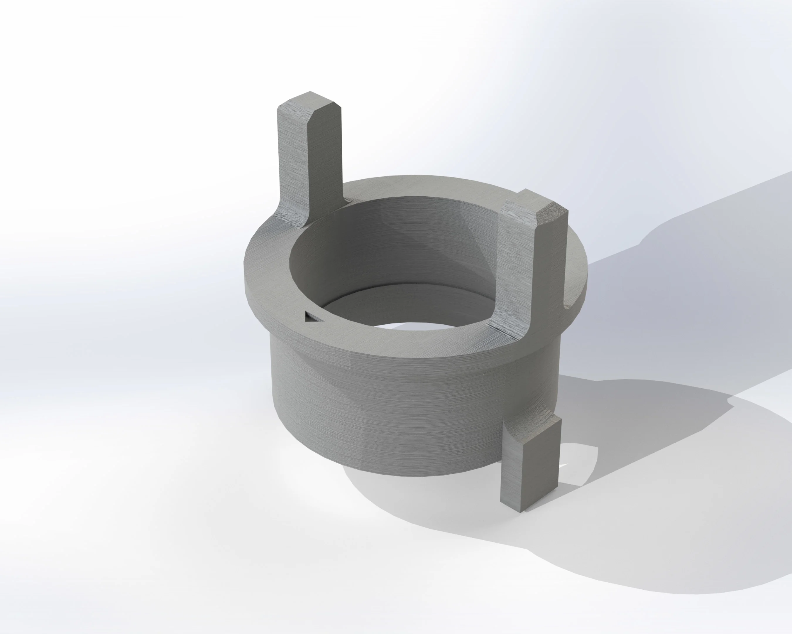
3D Printed Replacement Car Parts
A couple of replacement parts for my 1986 Mazda RX7 designed in CAD. The hood rests are printed in TPU as is the upper shifter seal. The hood rests work perfectly. They have been in place on my vehicle for about a year now without issue. The upper shifter seal is a modification of the original design so that it functions better as TPU instead of rubber. The uper shifter seal mates with the OEM lower seal. I've had it in place for a year aswell. The OEM turn signal cancel linkage has a tendency to "pop" out of place after roughly 40 years. A slight modification was incorporated to prevent this. It is printed in ABS.